


| A Pair of Mark III were purchased from a man who got them out of a barn where they were stored in boxes. They looked awful, smelled bad but they still worked with some hum! First up was the power supply. This from Joe Curcio is a regulated one for the plate and screen. I assembled the board to keep costs down. | 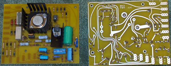 |
| New boards were purchased for the Driver as the old boards looked bad and smelled too! I stuffed them with metal film resistors and poly capacitors and a ceramic tube socket. This driver is the same as the original just a much better board. | 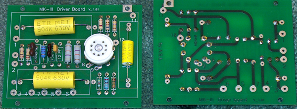 |
| I located by accident a pair of black Mark III chassis as well as many many packs of NOS hardware. Here are the black beauties that will become the new Mark III's. Still has the thick old plastic covering each. Never could get enough information to find out if these were made by Dynaco or where an aftermarket set. | 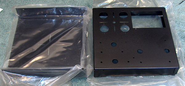 |
| Transformers were taken apart and cleaned. The Iron was painted black and the bell housings were painted silver for contrast. These transformers had the desired cloth leads. In mounting them to the deck I added a washer to the top as almost every Mark III I have worked on had transformers sitting cockeyed because the tabs that the screw goes through is not stiff enough. The washer helps stiffen the hole area and puts contact closer to the transformer housing where the tab is somewhat stiffer. Notice too the ceramic gold contact final Tube sockets. | 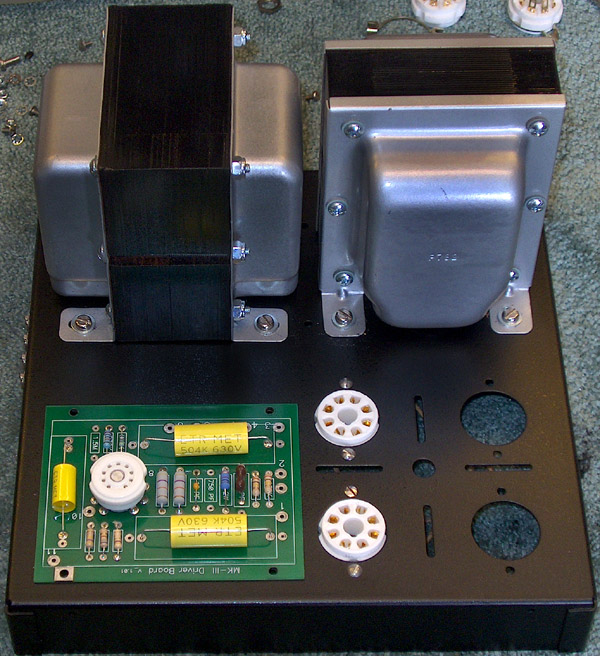 |
| Under the chassis, wiring is laid out and started. This amp is wired with a star grounding system. The ground point for the whole amp is in the center and is a loop of copper wire soldered to terminals and layered on the bolt with star washer - first terminal, star washer - second terminal then the nut so that when tightened down, the star washer "bites" into the chassis and each of the terminals for a good solid mechanical connection. | 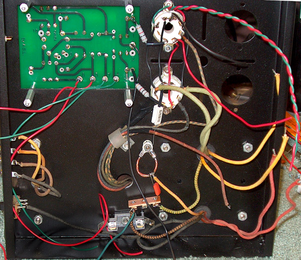 |
| Here the Joe Curico regulated B+,. Screen and filament power supply is installed. The wired board on the right contains 14 electrolytic capacitors. The voltage of the original can electrolytic capacitor was actually too small, rated at 525 volts and with voltages that high with a tube rectifier, and reaching 550 volts with the new full rectifier diode array the new cap set has a voltage rating of 700 volts. Each capacitor pair was in series with a dividing resistor pair to equalize the voltage and total capacity was greatly increased. Be sure to see the Schematics page for capacitor bank information. The B+ supply filter was increased from 20uf/525 to 157/750! | 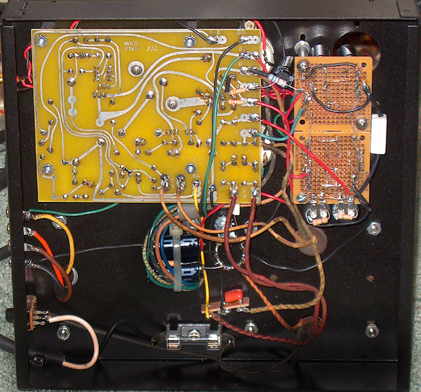 |
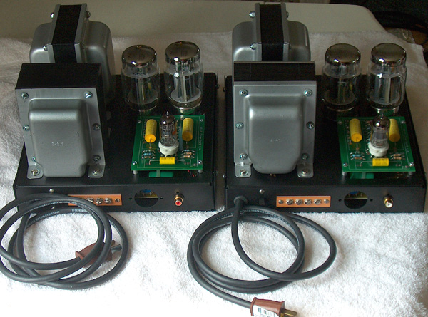
| Here is the amp after final assembly and checkout. We hit 64.7 watts before clipping which is just a bit more than when new. Amp is very quiet and the sound is HUGE! No other words to describe. I ran these with my RF-7 Klipsch towers. Thunderous comes to mind for 120 watt system. I fed the pair with one of my modified PAT 4 as I did not have any PAS 3 in house at the time. Stereo separation and sound stage was astounding due in part to separate mono amps each with its own power supply. Really cuts the cross talk down to whatever the pre-amp and source material will give. | 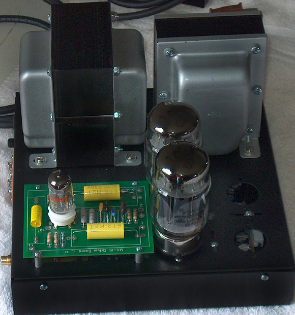 |
|
Here is the pair in all its glory. I cannot begin to tell you how many people were blown away by this pair of amps and how they sounded. When I told them this was 50 year old iron and a 50 year old design with just new updated components they just marveled! Note in the hole that was originally holding a socket for the PAM 1 pre-amp, you can just see the pot for adjusting bias and the test point is there as well. |
 |

[Home][Allied - R S][Dynaco][Hallicrafters][Heathkit][Lafayette][Radio's][Stereo Hi-Fi][Tape Recorder][Philco][News][Radio Collect][Tape Collect][Contact Us]
Copyright (c) 2007 R. David Adams. All rights reserved.