


| Fresh mostly complete Stereo 120. Often overlooked today due to early units having problems just going into feedback and literally "blowing up". Over the years many updates to stop this were introduced and the last models were some of the best early Transistor power amps. This unit will get a new CMOS power supply, all the Tip transistor upgrades that Dynaco made as well as upgraded power transistors. | 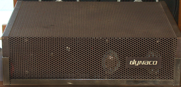 |
| Inside the unit shows a lot dirt due to the holes in the lid. Chrome is pitting, electrolytic capacitor is missing and wires burnt and melted. What a mess. We start with a complete tear down. Then we build up a new CMOS supply developed years ago by Frank Van Alstine over 24 years ago. All electrolytic capacitors on the driver boards will be replaced, resistors checked / replaced, all solid state devices replaced. Power supply electrolytic capacitors checked and replaced as needed as well as the large output capacitors. If the out put caps need replacing they will be replaced with computer grade with larger capacitance and higher working voltage. The out put caps will be by passed by large polyester caps as well. | 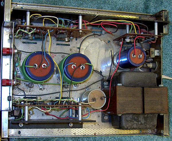 |
|
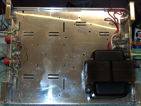
All the guts removed, The chrome cleaned and larger pits sanded down and chrome polished. Transformer was removed cleaned and painted. PC boards removed from the heatsinks, transistors and diodes removed. |
 |
| here is one channel done. Note the non polarized capacitors used and the mylar as well. This board had some kind of what looks like heat damage but turned out to be something spilled through the top cage. All the semiconductors were replaced and I was just waiting for my heat sinks for the two driver transistors on the right that will bolt on. | 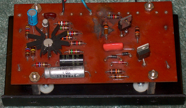 |
| Power supply board had more damage that looked like heat but was more spill through the top cage. Here all the parts were removed and he new CMOS regular circuit wired in. Check the schematic page for all the information. | 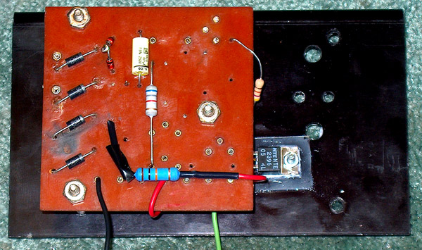 |
| Output transistors were removed and the heat sink cleaned. New outputs were installed using a larger insulator and lots of silicon heat transfer compound to be sure of good heat transfer as the heat sinks as used in the 120 are not as efficient as newer fined ones. I have experimented with adding a finned heat sink to the transistors as well but space is at a premium to the outside cage. | |
| Here is the finished product. All the power supply capacitors that were still in the unit were ok, and the output caps were fine as well. New caps are much smaller than the huge power supply cap that was missing, the new one was hot glued to the bottom and tie wrapped to one of the existing caps and then hot glued to make a firm setting. Notice also the addition of a fuse for the B+ feeding each of the power modules. | 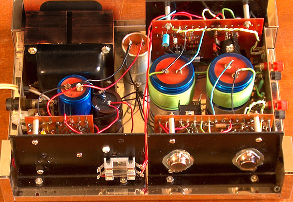 |
| Sanding and painting of the cage top was the last thing to do. I painted it with several coats of high temperature semi glass black and it really sets off the chrome a lot better than the original Dynaco brown. | 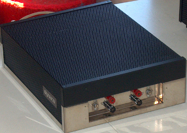 |
| Final front face. This unit was used in my system for three week driving Klipsch RF-7's and driven by a PAT 4 that I upgraded. the sound was amazing for an older solid state design. There are mod's for the 120 that can turn it into a CMOS amp but that also changes the sound. This delivers a good sound for the price and is in keeping with the Dynaco heritage of getting the most for the least. | 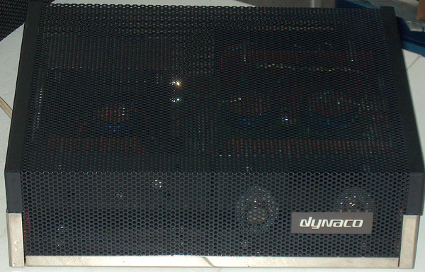 |

[Home][Allied - R S][Dynaco][Hallicrafters][Heathkit][Lafayette][Radio's][Stereo Hi-Fi][Tape Recorder][Philco][News][Radio Collect][Tape Collect][Contact Us]
Copyright (c) 2007 R. David Adams. All rights reserved.